 The terms 0 and 1 for electrical signals mean LOW and HIGH.
BARR/RJE conforms to the IBM standard for sending data to and receiving data from the PC asynchronous serial ports COM1 to COM4. You can use the serial port to drive printers or read data from other devices. This appendix lists serial port signals and printer cable specifications.
Signals for the 25-pin serial port connector on the PC are as follows:
|
Pin Number |
Name |
Direction |
Description |
|
1 |
PRO-GND |
-- |
Protective Chassis Ground. |
|
2 |
TXD |
out |
Transmit Data. |
|
3 |
RXD |
in |
Receive Data. Used for XON/XOFF flow control and receive data. |
|
4 |
RTS |
out |
Request-To-Send. Always set by BARR/RJE to 1. |
|
5 |
CTS |
in |
Clear-To-Send. Used for flow control. If CTS=0, then no data will be sent. This line can be jumpered to RTS to force CTS=1. |
|
6 |
DSR |
in |
Data-Set-Ready. Used for flow control by DOS. Can be used for flow control by BARR/RJE. To be compatible with DOS, pin 6 should be tied to pin 5. |
|
7 |
SIG-GND |
-- |
Signal Ground. |
|
20 |
DTR |
out |
Data-Terminal-Ready. Used for flow control when receiving on a COM port. BARR/RJE will set this to 0 to signal the remote device to temporarily suspend data transmission. |
 The terms 0 and 1 for electrical signals mean LOW and HIGH.
Signals for the 9-pin serial port connector on the PC are as follows:
|
Pin Number |
Name |
Direction |
Description |
|
3 |
TXD |
out |
Transmit Data. |
|
2 |
RXD |
in |
Receive Data. Used for XON/XOFF flow control and receive data. |
|
7 |
RTS |
out |
Request-To-Send. BARR/RJE always sets to 1. |
|
8 |
CTS |
in |
Clear-To-Send. Used for flow control. If CTS=0, then no data will be sent. This line can be jumpered to RTS to force CTS=1. |
|
6 |
DSR |
in |
Data-Set-Ready. DOS uses for flow control. BARR/RJE can also use for flow control. To be compatible with DOS, pin 6 should be tied to pin 8. |
|
5 |
SIG-GND |
-- |
Signal Ground. |
|
4 |
DTR |
out |
Data-Terminal-Ready. Used for flow control when you receive on a COM port. BARR/RJE will set this to 0 to signal the remote device to temporarily suspend data transmission. |
 The terms 0 and 1 for electrical signals mean LOW and HIGH.
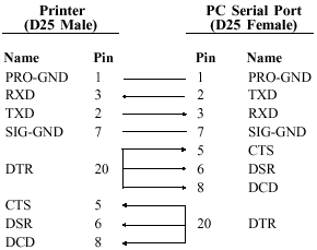
This type of printer cable is also called a null-modem cable. It has a D25 male connector that plugs into the printer and a D25 female connector that plugs into the PC serial port.

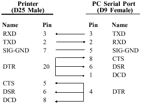
This type of printer cable is also called a null-modem cable. It has a D25 male connector that plugs into the printer and a D9 female connector that plugs into the PC serial port.
